WA2IAC's Ten Tec Triton II |
See also: Home 2011 Gear |
This page contains up-to-the-minute (!) information about my recently acquired Ten Tec Triton II...
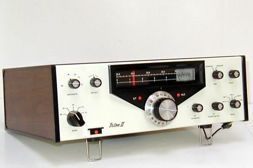
Above, the Ten Tec Triton II Serial number 00502. The dangly thing at the lower right is the indicator light for the add-on VFO stabilizer described below.
Immediate Mods/Actions:
- Clean out dust inside, but note this unit was very clean as received
- Acquire manual from Ten Tec (couldn't find it on the net; will post it here soon)
- Identify add-on PCB (see below)
- Test with 12a 12V switching power supply
- Added cork feet/shims/insulators to back power supply fin so fin doesn't touch the surface the Triton II is placed on.
Problems Found:
- Humm on AF filter option board (in CW1 and CW2 settings) - bad decoupler cap?
- Some noise on band select gang switches
- Dial pointer hangs (gets stuck) at extreme left
An Awesome Addition for VFO Stability
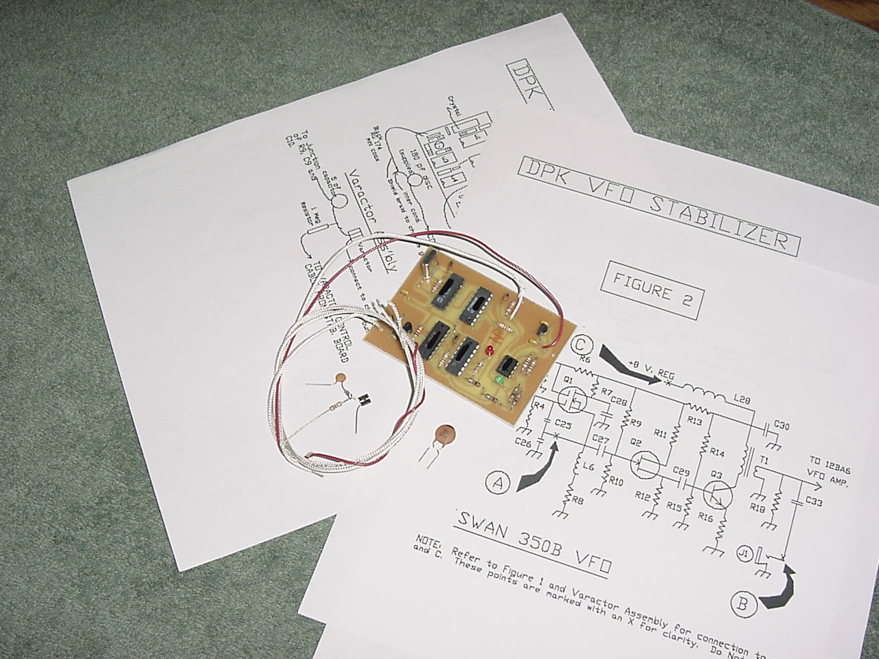
When I received the rig - and fortunately the Ten Tec manual (not included with the radio, and not findable on the 'net), I found an extra board inside (as had been described in the eBay entry). There was a wire running into the main tuning capacitor chamber, and thought "wow, that's an interesting add-on". I removed the PCB and found the callsign K4DPK on the foil side of the board (which hadn't been visible to the individual that sold me the rig). Some Googling rapidly revealed the PCB to be Phil, K4DPK's VFO stabilizer circuit. Rather than re-phrase what it's about, I've excerpted the information Phil had posted on the web. Apparently these have been made for many years, and I've got one of the old ones. Phil is still making this device, which will be of interest to anyone with a vintage VFO on their hands...
I gave Phil a call on the land line, and had a great chat with him. It turns out Phil's hamshack is predominantly Ten Tec! He's got nearly every major beast of Ten Tec's represented there. Phil is also a fan of AM, and told me that in addition to rebuilding some Hallicrafter receivers, he's building up a kilowatt rig for AM. It was such a pleasure and happenstance to run into Phil. We discovered some other things we have in common, which made for Phil having a good understanding of the trials and tribulations I've been through in the past few years. But, back to the VFO stabilizer...
From the K4DPK Web Page for the VFO Stabilizer circa 1/2011
DPK VFO Stabilizer.....Greatly reduces drift in conventional VFOs and PTOs. This device has been installed and proven effective in a great many older rigs. A partial list:
- Swan 350B Swan 500cx
- Heath HW-101, SB-102, SB104A
- Collins KWM2
- Kenwood TS-120, TS-520, TS-530S, TS-820S, TS-830S
- TenTec Triton IV, Corsair, Corsair II, 580 Delta, and Model 540
- Drake TR3, TR4, T4XC, R4C (sorry no TR7 or TR7A)
- Signal One CX7 and CX-11
- Yaesu FT-101, 901dm, 902
- many others including Hammarlund and Hallicrafters rigs.
Click the image below for a high-res image...
How the Stabilizer works:
The signal from a stable on-board crystal oscillator and a sampling of the signal from the rig's VFO are both processed through binary counters to develop a high degree of accuracy, then integrated to generate a control voltage.
This controlling voltage is applied to a varactor network across the tuned circuit of the VFO. The control voltage is used in a way that is inverse to the direction of drift, so drift is corrected as it happens.
A built-in delay prevents the correction of fast frequency changes. This allows the circuit to "turn loose" when you turn the VFO knob, and then "re-grab" on the new frequency.
The high-quality glass epoxy control board measures approx. 2" X 3" and contains 5 integrated circuits, a stable crystal reference oscillator and on-board voltage regulation. It will mount inside the radio. No changes are made to the radio. There are simply four attachment points where the Stabilizer connects. These are clearly indicated on Installation Instructions supplied for your specific radio.
The price of the Stabilizer is $70 shipped in CONUS [circa 1/2011]. Installation is very simple and usually takes about an hour. There are no changes made to the transceiver. Only a few connections are made to existing points in the radio, and these are precisely shown on the drawings supplied for installation in your radio.
History of the Stabilizer: The idea for this circuit started in Europe, and in the 1980s my good friend Jim Miles, K5CX (SK) adapted it for use in his homebrew transceiver. At the time, we were interested in operating HF Packet, so I installed a stabilizer in my TS-530s. There was an immediate improvement in rig stability. I could stay connected to the packet cluster for hours instead of minutes. By making changes in the binary structure, crystal frequencies and controlling elements, I've been able to adapt the circuit to fit a great many radios, and, as indicated earlier, they have been quite successful.
Phil Chambley, Dr.
28 East Camelia Rd. NE
Rome, GA 30161
K4DPK@comcast.net
Design ©2002-2011, InfoWeb.net Content ©1971-2011 WA2IAC